
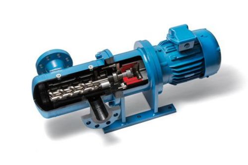
Magnetically Coupled Lube Oil Pumps for High Inlet Pressure.
Technical Challenges of High Inlet Pressure Applications.
Three screw pumps are commonly used as lube oil pumps for compressors, gear boxes, turbines and other rotating equipment. Their popularity stems from the efficient, reliable and long lasting service they provide.
There are some lube oil applications where the pump is exposed to high inlet pressure. This poses a huge challenge for the pump seal solution and pump construction. Special sealing arrangements, often with balanced mechanical seals, can achieve this task. The pump cost is driven up.
Also, high inlet pressures can create high axial forces on the main screw that lead to high bearing loads.
Pumps with magnetic coupling.
Pumps with magnetic coupling are able to meet the technical challenges of high inlet pressure applications. Compared to a mechanically sealed pump a magnetically coupled pump has no rotating seal. The pump is hermetically sealed and leak free. Lube oil systems stay clean and no disposal of dripping oil is required.
Another huge advantage of the magnetic coupling is the axial thrust compensation: The magnetic coupling design eliminates the axial force resulting in only minimal load on the ball bearing due to the geometrical conditions.
The initial investment in a magnetically coupled pump is relatively high. However, the running costs are then considerably lower. The total cost of a pump with magnetic coupling is therefore lower.
How does a magnetic coupling work?
The outer rotor – a magnetic assembly containing powerful permanent magnets - is attached to the motor shaft. The pump housing and drive screw are hermetically sealed by a containment can. The inner rotor is attached to the pump shaft and contains strong and durable rare earth magnets.
The motor torque is transferred through the containment can without contact to the pump shaft through magnetic forces.
How does the axial thrust compensation work?
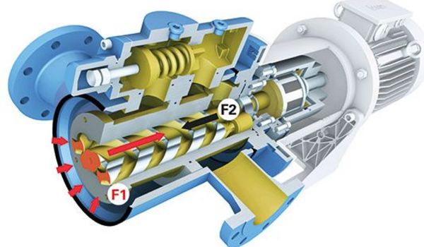
Drive screw.
High inlet pressure acts directly on the face of the main drive screw as well as the idler screws (F1). Some of the force is compensated on the pressure side of the main screw (F2). However a resulting axial force would normally create a high axial load on the bearing. Not so in the case of a magnetic coupling.
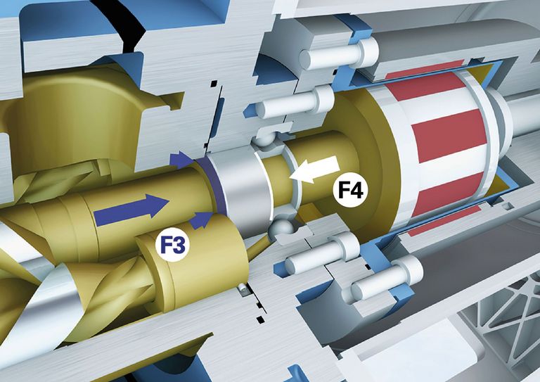
Balancing cylinder.
The balancing cylinder is exactly dimensioned so that the axial forces (F3 and F4) resulting from the pressures acting on its faces largely minimize the axial loads.
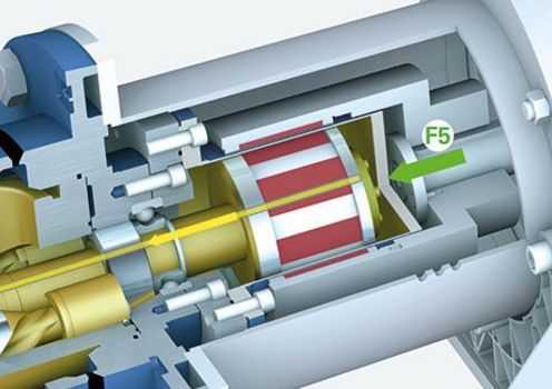
Magnetic coupling.
Due to a bore through the center of the drive screw the suction side pressure conditions are also present within the containment can of the magnetic coupling. Because of this this special design a force (F5) is created by the lube oil that compensates the residual axial thrust on the main spindle. The load on the bearing is minimized leading to long, trouble free operation.
06.04.2020